


mLink RGBW LED Controller Module
£4.99
VAT included
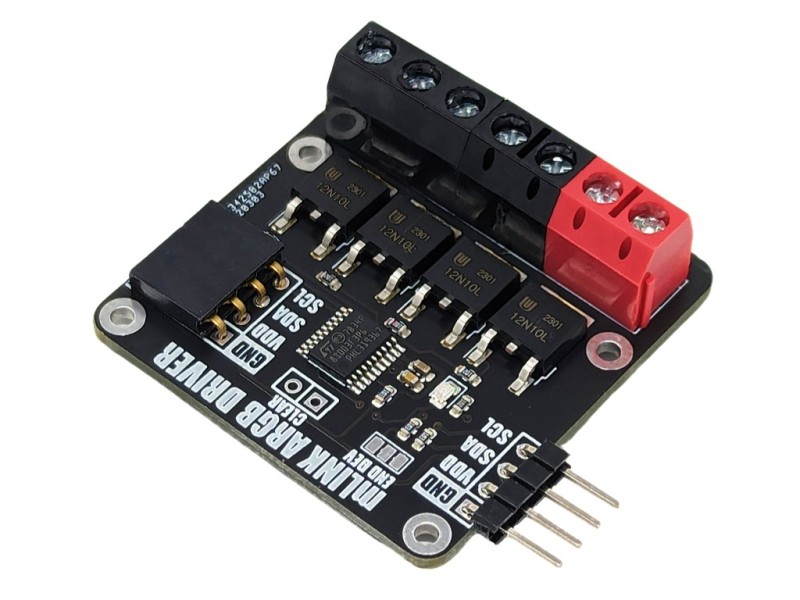
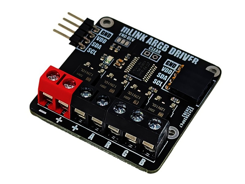
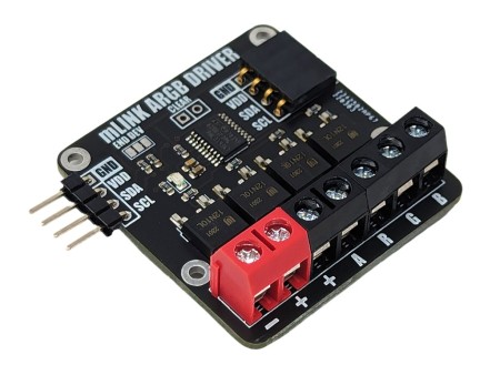
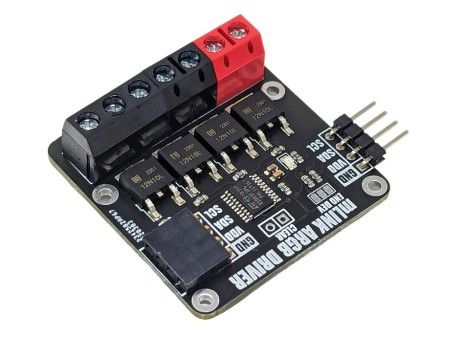
The mLink RGBW LED controller is a serial I2C module designed to allow a microcontroller such as an Arduino to control common types of RGB (red-green-blue) and RGBW (red-green-blue-white) LED light strips. The module has screw terminals for connecting the light strips power supply and its +Ve, -red, -green, -blue, and optionally -white connections. It is capable of controlling 5V, 12V, & 24V LED strips that require a +Ve supply with -ve RGB(W) control inputs at up to a total of 2A per channel.
When connected to a microcontrollers I2C interface each LED output can be controlled independently with up two 256 different levels of brightness allowing for a combined RGB colour palette of over 16 million colours...
The mLink RGBW LED controller is a serial I2C module designed to allow a microcontroller such as an Arduino to control common types of RGB (red-green-blue) and RGBW (red-green-blue-white) LED light strips. The module has screw terminals for connecting the light strips power supply and its +Ve, -red, -green, -blue, and optionally -white connections. It is capable of controlling 5V, 12V, & 24V LED strips that require a +Ve supply with -ve RGB(W) control inputs at up to a total of 2A per channel.
When connected to a microcontrollers I2C interface each LED output can be controlled independently with up two 256 different levels of brightness allowing for a combined RGB colour palette of over 16 million colours. Additionally, either predefined or user defined RGB colour cycling modes can be selected which can run independently of the microcontroller.
For Arduino users you can use the mLink library (see below for library and examples) to control any type of mLink module. Only one single instance of the library is needed to control multiple types of mLink modules resulting in very little resources overhead and therefore making it great for Arduinos with small amounts of memory and pin counts.
For Raspberry Pi users we have a Python module which can be installed via pip or downloaded and installed directly from our forum. Please see the mLink Python forum thread for requirements and download link here
Module specifications:
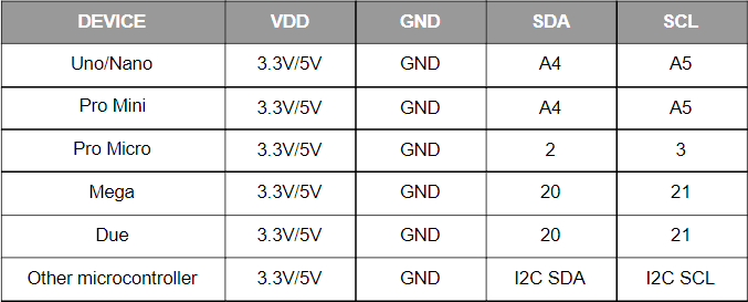
Module code: 					HCMODU0185
Supply Voltage (VDD): 			3V to 5.5V
Module current consumption:		7mA
Interfaces:					I2C, LED power in (+ & -), - red driver (R), -green driver (G), - blue driver (B), - white/aux driver (A)
I2C Interface speed: 				400kbits/s (fast mode)
I2C default address (HEX): 		0h53
LED voltage (max):				28V DC
LED current (max):				6A DC / 2A per RGBW output
Maximum number of modules: 		5 with pullups fitted, 112 with pullups removed*
Module dimensions (inc headers):	47.5mm x 40.5mm x 14mm
*Note the maximum number of connected modules will depend on cable lengths and power requirements of each module. Do not exceed 5 mLink modules connected in series with all fitted to all modules.
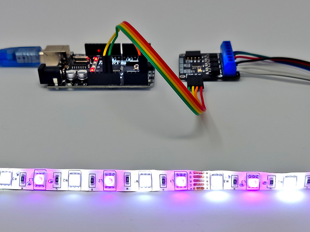
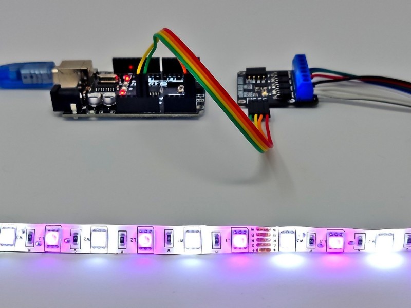
Arduino Connection Example:
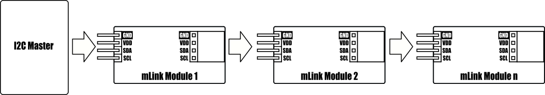
When used with microcontollers such as Arduino the mLink relay modules can be controlled via a serial I2C interface.
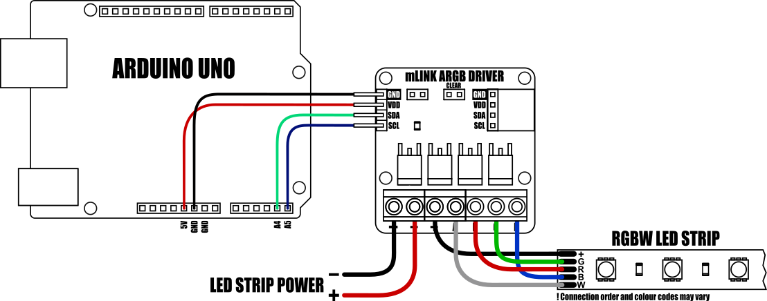
Because the modules use an I2C interface this also means multiple modules can controlled from a single Arduinos I2C interface simply by daisy-chaining them together. Note to control multiple mLink modules of the same type requires changing the default I2C address of the additional modules. See mLink Library Quick Start Guide for how to do this.
Arduino RGB(W) Colour example:
This sketch demonstrates how to control the brightness of the individual red, green, blue, and white LEDs on an RGB/RGBW LED strip. The sketch will step through each colour in sequence.
-
#include "mLink.h" // Include the library
-
-
mLink mLink; // Create an instance of the library
-
-
#define I2C_ADD 0x53 // Default I2C address
-
-
-
void setup()
-
{
-
mLink.init(); // Initialise the library
-
-
mLink.write(I2C_ADD, RGBW_BRIGHTNESS, 255); // Set brightness to maximum
-
}
-
-
-
void loop()
-
{
-
mLink.write(I2C_ADD, RGBW_R_LEVEL, 255); // Turn just the red LEDs on
-
mLink.write(I2C_ADD, RGBW_G_LEVEL, 0);
-
mLink.write(I2C_ADD, RGBW_B_LEVEL, 0);
-
mLink.write(I2C_ADD, RGBW_W_LEVEL, 0);
-
-
delay(1000);
-
-
mLink.write(I2C_ADD, RGBW_R_LEVEL, 0); // Turn just the green LEDs on
-
mLink.write(I2C_ADD, RGBW_G_LEVEL, 255);
-
mLink.write(I2C_ADD, RGBW_B_LEVEL, 0);
-
mLink.write(I2C_ADD, RGBW_W_LEVEL, 0);
-
-
delay(1000);
-
-
mLink.write(I2C_ADD, RGBW_R_LEVEL, 0); // Turn just the blue LEDs on
-
mLink.write(I2C_ADD, RGBW_G_LEVEL, 0);
-
mLink.write(I2C_ADD, RGBW_B_LEVEL, 255);
-
mLink.write(I2C_ADD, RGBW_W_LEVEL, 0);
-
-
delay(1000);
-
-
mLink.write(I2C_ADD, RGBW_R_LEVEL, 0); // Turn just the white LEDs on
-
mLink.write(I2C_ADD, RGBW_G_LEVEL, 0);
-
mLink.write(I2C_ADD, RGBW_B_LEVEL, 0);
-
mLink.write(I2C_ADD, RGBW_W_LEVEL, 255);
-
-
delay(1000);
-
}

For more information including documentation and the mLink library please visit this products forum page here:
https://forum.hobbycomponents.com/viewtopic.php?f=131&t=3004
HCMODU0185
10 Items
Specific References

The mLink RGBW LED controller is a serial I2C module designed to allow a microcontroller such as an Arduino to control common types of RGB (red-green-blue) and RGBW (red-green-blue-white) LED light strips. The module has screw terminals for connecting the light strips power supply and its +Ve, -red, -green, -blue, and optionally -white connections. It is capable of controlling 5V, 12V, & 24V LED strips that require a +Ve supply with -ve RGB(W) control inputs at up to a total of 2A per channel.
When connected to a microcontrollers I2C interface each LED output can be controlled independently with up two 256 different levels of brightness allowing for a combined RGB colour palette of over 16 million colours...