Hobby Components SmartLCD...
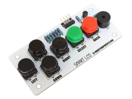
The SmartLCD Keypad Kit is an optional add-on for the Hobby Components SmartLCD (HCMODU0122)....
£6.99

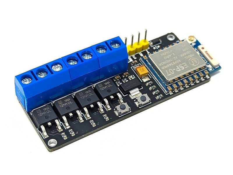


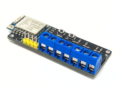

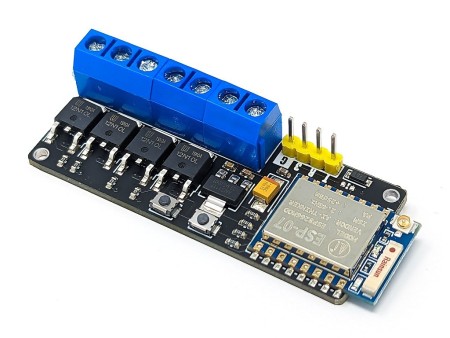

The ESP-ARGB is a general purpose RGB or RGB+W LED light controller based on the popular Expressive ESP8266 wireless microcontroller. It combines an ESP8266 ESP-07 wireless module with four MOSFET transistors. These transistors are connected to the ESPs PWM output pins making it easy to perform independent power control of up to 4 connected devices. Each transistor can switch up to a maximum current of 2A and a maximum voltage of 12V DC.
The ESP-ARGB is a general purpose RGB or RGB+W LED light controller based on the popular Expressive ESP8266 wireless microcontroller. It combines an ESP8266 ESP-07 wireless module with four MOSFET transistors. These transistors are connected to the ESPs PWM output pins making it easy to perform independent power control of up to 4 connected devices. Each transistor can switch up to a maximum current of 2A and a maximum voltage of 12V DC.
The module comes shipped with the WLED firmware pre-installed so out of the box it is ready to connect to your WiFi network and controlled via the WLED Android or iOS, or even via a web browser on your computer. Just connect your LED strip and power supply to the module and you're ready to go. Additionally as the module runs the WLED firmware it is also compatible with home automation software such as Home Assistant.
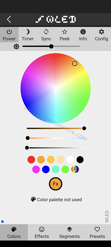
WLED app main screen
Alternatively, if you wish to write your own firmware it is compatible with the Arduino IDE (requires an additional USB to serial adapter for uploading sketches). From the Arduino IDE the transistors can be controlled using just the standard Arduino digitalWrite() and analogWrite() commands.
Although the module is designed primarily for driving standard RGB or RGBW LED lighting strips it can be used to drive any other device that can be switched via a transistor (-Ve switched). For example the module can be used as a DC motor speed controller for up to 4 motors.
Programming can be achieved via the modules serial interface. Please note: To program the module via a PC an additional USB to serial / FTDI adapter will be required. To simplify the programming process the module comes fitted with program and reset buttons allowing it to be manually put in and out of programming mode. For instructions on how to program via the Arduino IDE please see forum post.
Product code: HCMODU0234
Supply Voltage (Via +/- screw terminals): 5 to 12V DC
Module current consumption (Sleep): 10mA
Module current consumption (connected to WiFi network): 215mA
ARGB driver: 2A per channel / 6A combined, -Ve switching (0.9V Vf)
PWM resolution: 8bits (256 levels)
Interfaces: 4x MOSFET drivers + power via screw terminals, serial programming interface, program and reset buttons.
ESP8266 type: ESP-07
ESP8266 clock: 80MHz
ESP8266 Flash: 8Mbit
ESP8266 Transmit power: 802.11b: 16±2 dBm (11Mbps)
802.11g: 14±2 dBm (54Mbps)
802.11n: 13±2 dBm (HT20, MCS7)
Dimensions (LxWxH): 62.5mm x 23mm x 14mm
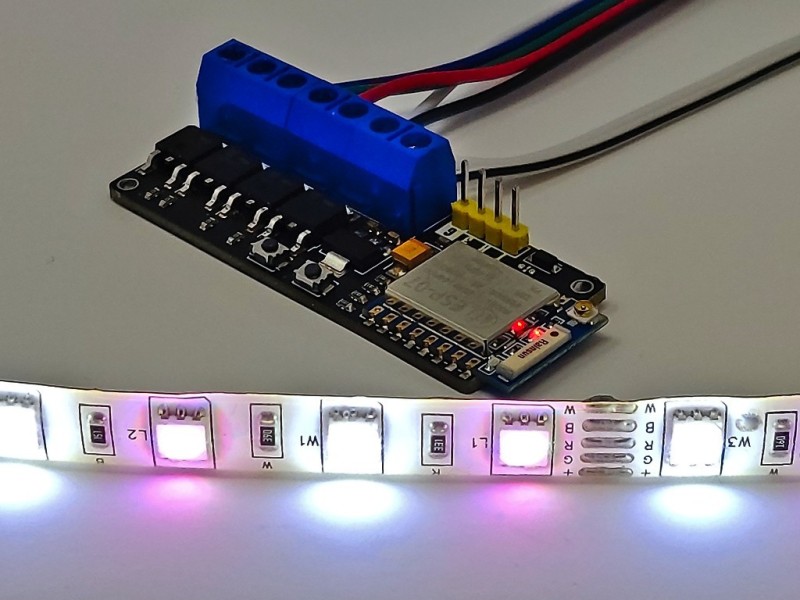
Example 12V RGBW light strip connection:
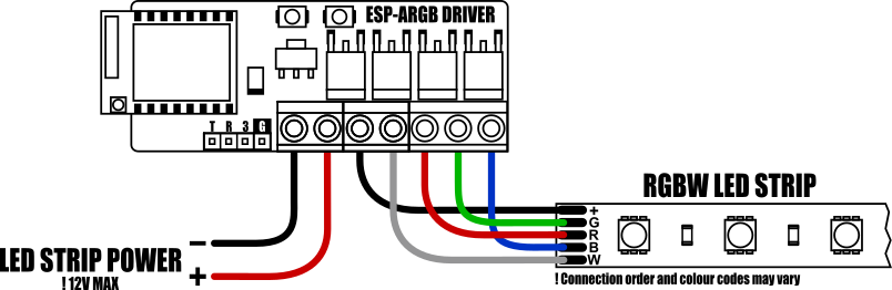
The module can drive 12V RGB light strips at up to 2A per channel. If your light strip has an additional white input this can be connected to the driver A (aux) terminal.
A single power supply for both the module and light strip can be connected to the modules + and - screw terminal inputs (!12V max).
Arduino IDE setup guide:
The module is compatible with the Arduino IDE via the board manager feature. The latest version of the Arduino IDE can be downloaded from the official Arduino website here:
https://www.arduino.cc/en/software
Once installed you will need to add board support for ESP8266 devices. To do this just follow steps 1 & 2 in our blog post here:
[https://blog.hobbycomponents.com/?p=937]
Arduino IDE board settings:
Board: Generic ESP8266 Module
Port: The COM port of your USB interface module.
Crystal Frequency: 26MHz
Flash Frequency: 40MHz
Flash mode: DIO
Reset Method: dtr
Upload Speed: 115200
Flash Size: 1MB (FS64KB OTA:~470KB)
CPU Frequency: 80MHz
You can leave any additional settings to their defaults.
Programming the ESP-ARGB
To interface this module to your PC you will need an additional USB to serial interface adapter. The serial interface is compatible with both 3.3V and 5V TTL adapters:
https://hobbycomponents.com/usb-interfa ... al-adaptor
https://hobbycomponents.com/usb-interfa ... rt-adapter
https://hobbycomponents.com/usb-interfa ... le-adaptor
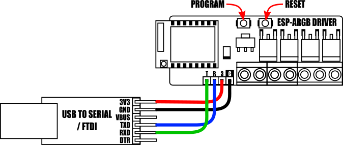
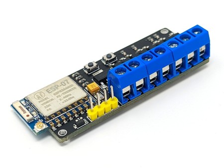
Connect the USB to serial adapter to the module's serial interface as shown above.
Note, if the module is powered from the + & - screw terminals the 3V pin (labelled 3) on the modules serial header becomes a 3.3V output. Therefore in this configuration do not connect the serial interfaces 3.3V supply pin to the module.
To upload a sketch from the Arduino IDE the module must first be manually put into programming mode. To do this, locate the modules PROGRAM and RESET buttons (see diagram above), then hold down the PROGRAM button whilst pressing and then releasing the RESET button.
The module will now be in programming mode and will stay in this mode until the module is reset or power is removed.
After uploading your sketch the module can be put back into run mode by pressing the RESET button.
The SmartLCD Keypad Kit is an optional add-on for the Hobby Components SmartLCD (HCMODU0122)....
PLEASE NOTE THAT THIS KIT IS NOW SHIPPED WITH OUR UNO+ Development Board (See SKU:...
The 1602 SmartLCD module is a serially controlled 2 line by 16 character alphanumeric...
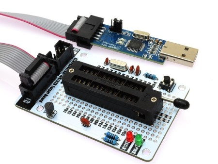
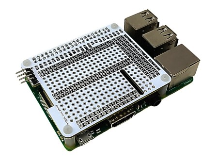
This prototyping/programming board is designed for use with the Atmel ATMega48P, ATMega168P,...
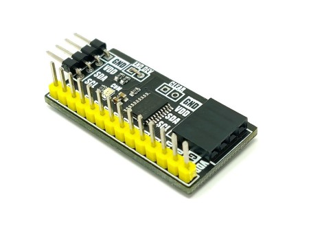
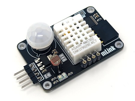
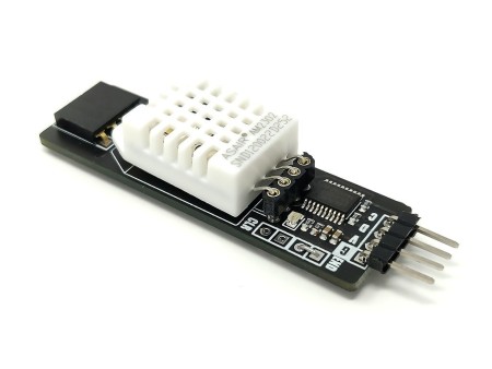
The mLink port expander is a serial (I2C/IIC) digital I/O module. It allows you to add 12...
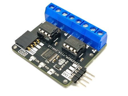
The mLink L9110 motor controller is a serial (I2C) 2 channel DC motor driver that is capable...
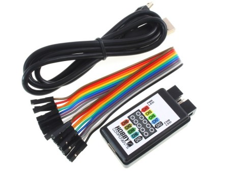
Our hugely popular low cost 8 channel analyser (HCTEST0006) is designed to work with the...
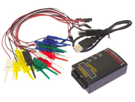
The Hobby Components logic analyser can capture up to 16 separate channels of 3.3V or 5V logic...
We've partnered up with the fabulous guys over at EDTracker to bring to you the EDTracker...
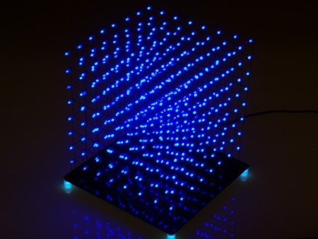
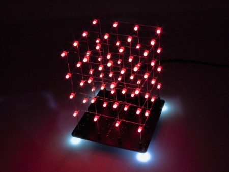
LED light cubes are a hugely popular and fun project. With this kit (HCKITS0050) you will have...
The ESP-ARGB is a general purpose RGB or RGB+W LED light controller based on the popular Expressive ESP8266 wireless microcontroller. It combines an ESP8266 ESP-07 wireless module with four MOSFET transistors. These transistors are connected to the ESPs PWM output pins making it easy to perform independent power control of up to 4 connected devices. Each transistor can switch up to a maximum current of 2A and a maximum voltage of 12V DC.