


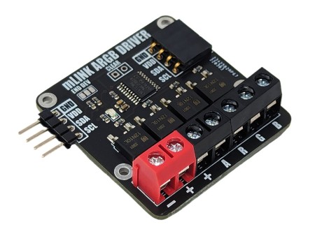
mLink WS2812 RGB LED Controller
£3.99
VAT included
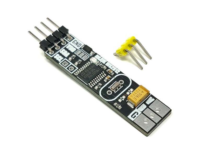
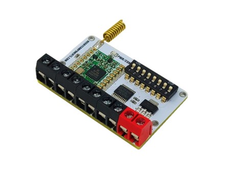
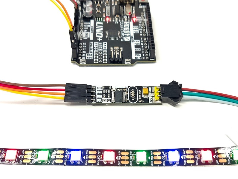
The mLink WS2812 LED driver is a serial (I2C) module intended for driving WS2812 5V RGB LEDs. It is capable of independently controlling up to 200 LEDs via the WS2812s serial interface.
The module is capable of generating the precise timings required by these LEDs and its 200 LED buffer can store the individual RGB state of each LED in full 24 bit colour. This removes the memory and processing requirements of the host microcontroller which is especially useful for low power 8-bit microcontrollers with limited amounts of RAM and processing power.
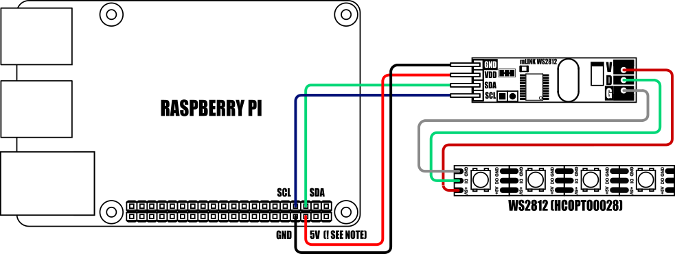
Compatible with microcontrollers equipped with an I2C interface, including popular Arduino models, wireless ESP devices, and Raspberry Pi, this module offers versatile control options. As part of the mLink series, it seamlessly integrates with other mLink modules. This means you can easily daisy-chain multiple mLink modules, enabling centralised control through a single serial interface.
For Arduino users you can use the mLink library (see our support forum for library and examples) to control any type of mLink module. Only one single instance of the library is needed to control multiple types of mLink module, resulting in very little resource overhead and therefore making it great for Arduinos with small amounts of memory and pin counts.
For Raspberry Pi users we have a Python module which can be installed via pip or downloaded and installed directly from our forum. Please see the mLink Python forum thread for requirements and download link here: viewtopic.php?f=131&t=3062&p=8592#p8592![]()
| Module code: | HCMODU0197 |
| Supply voltage (VDD): | 4.5V to 5.5V |
| Current consumption (idle): | 6.5mA |
| LED type: | WS2812 5V RGB LEDs |
| Maximum number of LEDs per module: | 200* |
| Number of colours: | Full 24bit (16,777,215) colours |
| Brightness: | 255 levels with separate on/off control |
| Interfaces: | 4 pin male mLink header, Large WS2812 solderable pads with option 0.1” pin header |
| I2C Interface speed: | 400kbits/s (fast mode) |
| I2C default address (HEX): | 0h5E |
| Maximum number of modules: | 5 with pullups fitted, 112 with pullups removed** |
| Module dimensions ex headers (LxWxH): | 40.5mm x 11mm x 5mm |
*Note the maximum number of connected modules will depend on cable lengths and power requirements of each module. Do not exceed 5 mLink modules connected in series with I2C pullups fitted to all modules. For disconnecting pullups see forum post.![]()
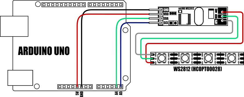
Important note: If your LED strip has more than 24 LEDs then the LED strip MUST be powered via an external 5V power supply.
![]()
Important notes:
If your LED strip has more than 24 LEDs then the LED strip MUST be powered via an external 5V power supply. The maximum number of LEDs that can be driven from the Raspberry Pi / mLink module may also be limited by your Raspberry Pis PSU
When connecting to a Raspberry Pi the mLink modules I2C pullup resistors should be removed. See the 'Removing the modules I2C pullup resistors' section below for more information.
![]()
Factory Reset:
Should you wish to restore the module back to its factory default configuration, this can be done by manually forcing a factory reset. All mLink modules include a set of pads labeled clear: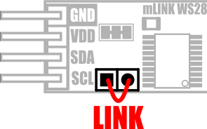
To perform a factory reset carefully link the two pads together with a piece of wire or with something conductive such as a paperclip. Whilst linked, connect power to the module via the VCC and GND connections. Wait a few seconds and then remove the short from the pads. The module's settings, including its I2C address, should now be restored back to factory defaults.
Removing I2C pullups:
If your development board already has pullups for its I2C interface fitted, or you wish to connect more than 5 mLink boards to the same I2C interface, then you can remove the pullups for the additional boards by cutting the tracks between the solder pads shown below.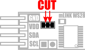
![]()
mLink Arduino Library, Python Module, Specifications File and Register Map are available on our support forum here.
HCMODU0197
10 Items
Specific References
16 other products in the category
Hobby Components Arduino...
Building your own hardware is always fun especially when it's combined with the Arduino...
£5.99
£3.99
- On sale!
Hobby Components Uno Plus
This is our lower cost alternative to the standard R3 Uno, but in this case lower cost doesn't...
£5.99
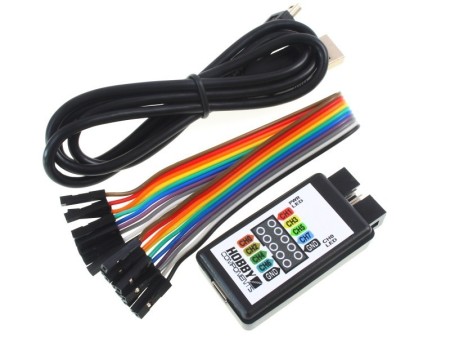
Hobby Components USB 8CH...
Our hugely popular low cost 8 channel analyser (HCTEST0006) is designed to work with the...
£8.49
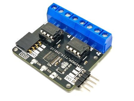
mLink L9110 DC Motor...
The mLink L9110 motor controller is a serial (I2C) 2 channel DC motor driver that is capable...
£6.99
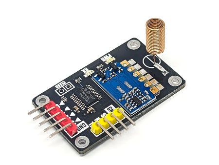
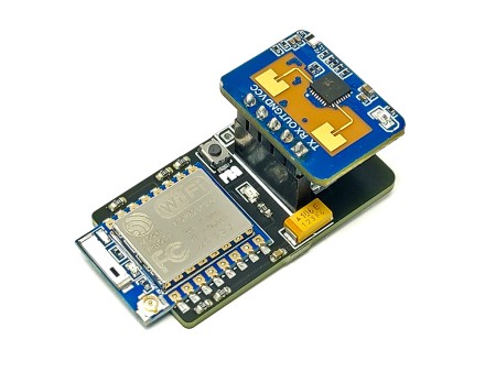
SmartRFy Digital Rx Module
The SmartRFy digital Rx module provides a set of 4 digital output pins which can be remotely...
£3.99
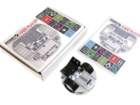
Maze Runner - Arduino...
This kit allows you to build your very own maze solving robot. It comes complete with...
£34.99
- Currently Out of Stock
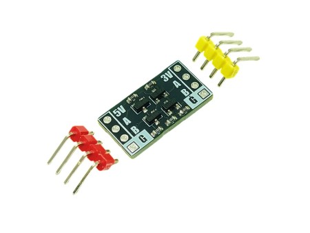
Hobby Components 2 Channel...
This module uses a set of transistors with pullup resistors to provide a 2 channel...
£1.49
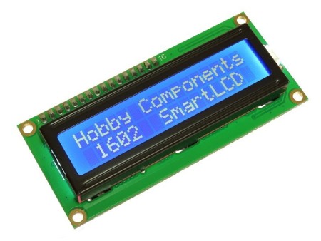
Hobby Components 1602 SmartLCD
The 1602 SmartLCD module is a serially controlled 2 line by 16 character alphanumeric LCD...
£5.49
The mLink WS2812 LED driver is a serial (I2C) module intended for driving WS2812 5V RGB LEDs. It is capable of independently controlling up to 200 LEDs via the WS2812s serial interface.
The module is capable of generating the precise timings required by these LEDs and its 200 LED buffer can store the individual RGB state of each LED in full 24 bit colour. This removes the memory and processing requirements of the host microcontroller which is especially useful for low power 8-bit microcontrollers with limited amounts of RAM and processing power.