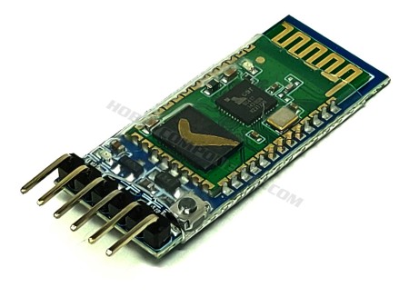
ENC28J60 Ethernet LAN / Network Module
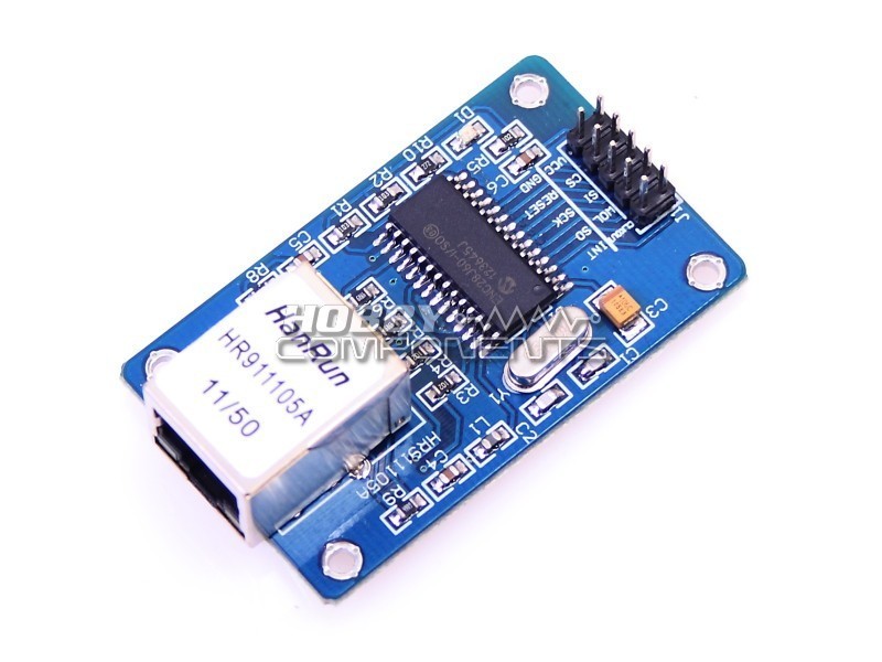
ENC28J60 Ethernet Module utilizes the new Microchip ENC28J60 Stand-Alone Ethernet Controller IC featuring a host of features to handle most of the network protocol requirements. This Ethernet LAN module connects directly to most microcontrollers.
ENC28J60 Ethernet Module utilizes the new Microchip ENC28J60 Stand-Alone Ethernet Controller IC featuring a host of features to handle most of the network protocol requirements. This Ethernet LAN module connects directly to most microcontrollers.
Description:
- Ethernet LAN Module for Arduino/AVR/LPC/STM3
- ENC28J60 Ethernet chips
- Can be easily mounted with the MCU
- Network Interface: HR911105A
- Supply Voltage: 3.3 V (5V Tolerant DIO)
- 25Mhz crystal oscillator
- Size (L x W x H): Approx. 2.3 x 1.3 x 0.7 inch / 58 x 34 x 17 mm
| PINOUT | |
|---|---|
| PIN | DESCRIPTION |
| 1 | CLK OUT |
| 2 | INT |
| 3 | WOL |
| 4 | SO |
| 5 | SI |
| 6 | SCK |
| 7 | CS |
| 8 | RES |
| 9 | +3.3V |
| 10 | GND |
EXAMPLE CODE
ARD_Ethernet_Module_HCARDU0028_Example.pde
/* FILE:    ARD_Ethernet_Module_HCARDU0028_Example.pde
   DATE:    28/07/12
   VERSION: 0.1

This is an example of how to use the HobbyComponents Arduino ethernet shield
(HCARDU0028). For this example to work you will need to download the appropriate
libraries available at:
http://forum.hobbycomponents.com/viewtopic.php?f=25&t=6
Unzip both libraries and copy them to your Arduino libraries folder.

This program will serve a basic webpage at the ip address specified below which will
allow you change the state of 4 relays. This program is intended to work with arduino
relay modules such as the HobbyComponents 4 channel relay module (HCARDU0025).


CONNECTIONS:

ETHERNET MODULE       ARDUINO BOARD
PIN 1  (CLK OUT)      N/A
PIN 2  (INT)          N/A
PIN 3  (WOL)          N/A
PIN 4  (SO)           DIO 12
PIN 5  (SI)           DIO 11
PIN 6  (SCK)          DIO 13
PIN 7  (CS)           DIO 10
PIN 8  (RES)          N/A
PIN 9  (VCC)          +3.3V
PIN 10 (GND)          GND


You may copy, alter and reuse this code in any way you like but please leave
reference to HobbyComponents.com in your comments if you redistribute this code. */

/* Include both ethernet libraries */
#include "etherShield.h"
#include "ETHER_28J60.h"

#define RELAY1_DIO 2  /* DIO pin used to drive relay 1 */
#define RELAY2_DIO 3  /* DIO pin used to drive relay 2 */
#define RELAY3_DIO 4  /* DIO pin used to drive relay 3 */
#define RELAY4_DIO 5  /* DIO pin used to drive relay 4 */

#define RELAY1_MASK 0 /* Bit mask for storing state of relay 1 */
#define RELAY2_MASK 1 /* Bit mask for storing state of relay 2 */
#define RELAY3_MASK 2 /* Bit mask for storing state of relay 3 */
#define RELAY4_MASK 3 /* Bit mask for storing state of relay 4 */


/* Used to store the current state of the relays */
int RelayState = 0;

/* MAC address of the ethernet shield. If you are using this on your
own network then the MAC address below will be fine, but remember if
you use more than one shield on your network they will need to be assigned
unique MAC addresses */
static uint8_t mac[6] = {0x54, 0x55, 0x58, 0x10, 0x00, 0x24};


/* The IP address of the shield. Make sure this matches the IP
   address range of your network and is not in use by any other
   device on it */

static uint8_t ip[4] = {192, 168, 1, 55};

/* The port number the shield will respond to. Use port 80
   for standard HTTP requests */

static uint16_t port = 80;

ETHER_28J60 e;


/* Initialise the ethernet interface and DIO pins */
void setup()
{
  e.setup(mac, ip, port);
  pinMode(RELAY1_DIO, OUTPUT);
  pinMode(RELAY2_DIO, OUTPUT);
  pinMode(RELAY3_DIO, OUTPUT);
  pinMode(RELAY4_DIO, OUTPUT);
}

/* Main program */
void loop()
{
  char* EthernetData;

  /* Has a page request been made? */
  if (EthernetData = e.serviceRequest())
  {

    /* Has the page link for relay 1 been pressed? */
    if (strcmp(EthernetData, "?relay=1") == 0)
    {
      /* If so then change the state of relay 1 */
      if (bitRead(RelayState, RELAY1_MASK))
      {
        bitClear(RelayState, RELAY1_MASK);
        digitalWrite(RELAY1_DIO, LOW);
      }else
      {
        bitSet(RelayState, RELAY1_MASK);
        digitalWrite(RELAY1_DIO, HIGH);
      }
    }

    /* Has the page link for relay 2 been pressed? */
    if (strcmp(EthernetData, "?relay=2") == 0)
    {
      /* If so then change the state of relay 2 */
      if (bitRead(RelayState, RELAY2_MASK))
      {
        bitClear(RelayState, RELAY2_MASK);
        digitalWrite(RELAY2_DIO, LOW);
      }else
      {
        bitSet(RelayState, RELAY2_MASK);
        digitalWrite(RELAY2_DIO, HIGH);
      }
    }

    /* Has the page link for relay 3 been pressed? */
    if (strcmp(EthernetData, "?relay=3") == 0)
    {
      /* If so then change the state of relay 3 */
      if (bitRead(RelayState, RELAY3_MASK))
      {
        bitClear(RelayState, RELAY3_MASK);
        digitalWrite(RELAY3_DIO, LOW);
      }else
      {
        bitSet(RelayState, RELAY3_MASK);
        digitalWrite(RELAY3_DIO, HIGH);
      }
    }

    /* Has the page link for relay 4 been pressed? */
    if (strcmp(EthernetData, "?relay=4") == 0)
    {
      /* If so then change the state of relay 4 */
      if (bitRead(RelayState, RELAY4_MASK))
      {
        bitClear(RelayState, RELAY4_MASK);
        digitalWrite(RELAY4_DIO, LOW);
      }else
      {
        bitSet(RelayState, RELAY4_MASK);
        digitalWrite(RELAY4_DIO, HIGH);
      }
    }

    /* Generate a new page with the current states of the relays */
    iUpdateRelays(RelayState);

    /* And send it back to the IP address that made the request */
    e.respond();
  }
}


/* This funtion generates a web page that shows the current state of
   the 4 relays and creates links to allow their states to be toggled.
   It requires a register of type int that holds the current state of
   the relays to be passed to it */

void iUpdateRelays(int RelayState)
{
    e.print("<H1>Web Remote</H1>");

    if (bitRead(RelayState, RELAY1_MASK))
    {
      e.print("RELAY 1: <A HREF='?relay=1'>ON</A><br>");
    }else
    {
      e.print("RELAY 1: <A HREF='?relay=1'>OFF</A><br>");
    }

    if (bitRead(RelayState, RELAY2_MASK))
    {
      e.print("RELAY 2: <A HREF='?relay=2'>ON</A><br>");
    }else
    {
      e.print("RELAY 2: <A HREF='?relay=2'>OFF</A><br>");
    }

    if (bitRead(RelayState, RELAY3_MASK))
    {
      e.print("RELAY 3: <A HREF='?relay=3'>ON</A><br>");
    }else
    {
      e.print("RELAY 3: <A HREF='?relay=3'>OFF</A><br>");
    }

    if (bitRead(RelayState, RELAY4_MASK))
    {
      e.print("RELAY 4: <A HREF='?relay=4'>ON</A><br>");
    }else
    {
      e.print("RELAY 4: <A HREF='?relay=4'>OFF</A><br>");
    }

}
Specific References
16 other products in the category
PT2262 Wireless Module...
The PT2262 (Tx) transmitter module is designed to be used in conjunction with the PT2272-M4...
- On sale!
GPS Module APM2.5 NEO-6M...
Cost effective, high-performance u-blox 6 based NEO-6 series of GPS modules, that brings the...
- Currently Out of Stock
ESP-12 (ESP8266) wireless...
This amazingly priced wireless module allows any microcontroller to connect to a 802.11b/g/n...
433MHz Wireless Receiver...
Low cost superheterodyne receiver designed to be used with transmitter HCMODU0088. The...
- On sale!
JY-MCU Bluetooth Serial...
The Hobby Components wireless Bluetooth module is intended to be used in conjunction with our...
- On sale!
2.4GHz 3dB SMA Antenna with...
High quality adjustable angle antenna with integrated SMA connector. Designed for low power...
TB387 20dBm High_Power...
The TB387 high powered module (HCMODU0089) provides a means of transmitting serial data over...
- Currently Out of Stock
IR Receiver Module Wireless...
- Remote control with 21 buttons
- Transmission Frequency: 38KHz;
- Launch Distance:...
HC-11 433MHz wireless...
The HC-11 433MHz Wireless Serial Port Module is based on the TI C1101 ultra low-power wireless...
- Currently Out of Stock
Master / Slave Bluetooth...
This class 2 Bluetooth module (HC-05) comes programmed with firmware that allows it to pass...
- Currently Out of Stock

