ESP-01S / ESP01S Relay...
This relay module is designed for the ESP-01s ESP8266 module. It features a 6 pin IDC socket...
- On sale!
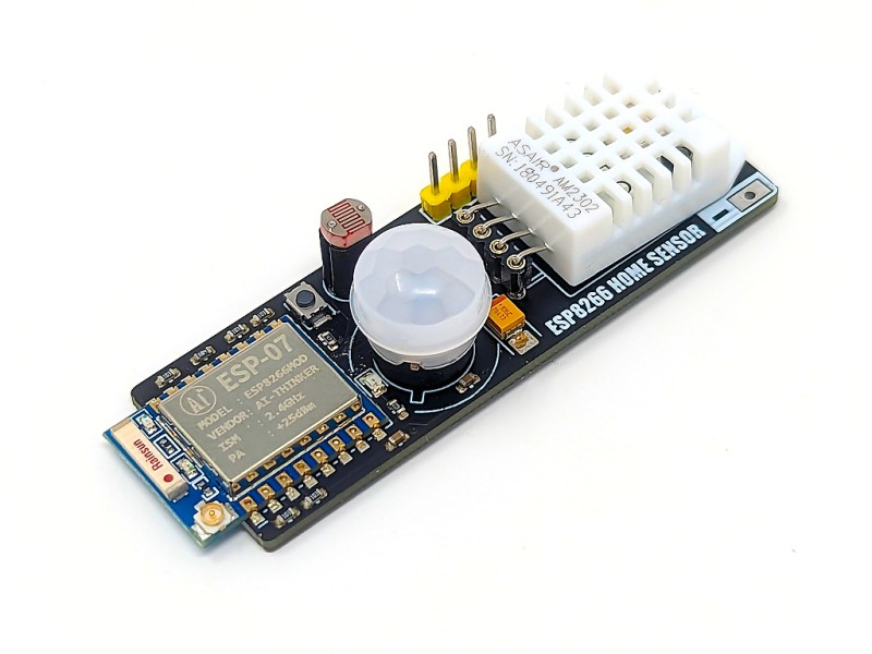


ESP8266 Home Sensor module is a wireless ESP2866 (ESP-07) based microcontroller development board which includes a DHT22 temperature and humidity sensor, an LDR light level sensor and a PIR motion detector. Its array of sensors makes it great for monitoring the environmental conditions and occupancy of a room wirelessly.
As of 22/05/24 this module is now shipped pre-flased with ESPHome firmware:

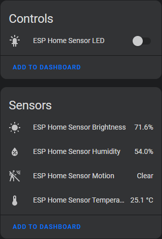
Features: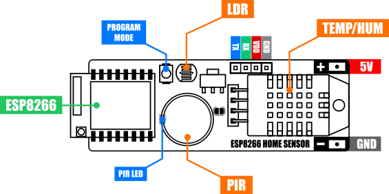
Specifications:
Product code: |
HCDVBD0045 |
Supply voltage: |
5V (or 3.3V via reg bypass mod - see below) via + & - solder pads or 5V & GND serial header pins |
Current consumption (deep sleep): |
2mA (inc module LED) |
Current consumption (modem sleep): |
21.5mA |
Current consumption (connected to WiFi network): |
215mA peek / ~72mA idle |
Interfaces: |
+ & - power solder pads, serial programming interface (5V tolerant), program mode button |
ESP8266 type: |
ESP-07 |
ESP8266 clock: |
80MHz |
ESP8266 Flash: |
8Mbit |
ESP8266 Transmit power: |
802.11b: 16±2 dBm (11Mbps) |
802.11g: 14±2 dBm (54Mbps) |
|
802.11n: 13±2 dBm (HT20, MCS7) |
|
Temperature sensor range: |
-40 to 80oC |
Temperature sensor resolution: |
0.1oC |
Humidity sensor range: |
0 to 100 %RH |
Humidity sensor resolution: |
0.1 %RH |
LDR sensor range: |
0V = 100%, 1V = Dark |
PIR Trigger on time: |
~4 seconds |
PIR Sensor angle: |
100 degree cone |
Sensor range: |
~3 to 5 metres |
Dimensions (LxWxH): |
68.8mm x 22.4mm x 18mm |
Programming the ESP Home Sensor
To interface this module to your PC you will need an additional USB to serial interface adapter. The serial interface is compatible with both 3.3V and 5V TTL adapters:
https://hobbycomponents.com/usb-interface/586-ch340-usb-to-ttl-serial-adaptor
https://hobbycomponents.com/usb-interface/41-ftdi-usb-serial-port-adapter
https://hobbycomponents.com/usb-interface/396-usb-to-uart-serial-interface-module-adaptor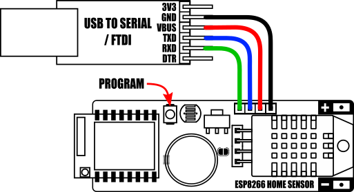
Connect the USB to serial adapter to the module's serial interface as shown above.
To put the module into programming mode hold down the program button (see image above) whilst plugging the USB adapter into your computer.
After uploading your sketch the module can be put back into run mode by removing and re-inserting the USB adapter or by cycling the module's power.
Basic sensor example:
This sketch uses the HCHomeSensor Arduino library to read the sensors and output their states to the serial monitor
3D Printer Case: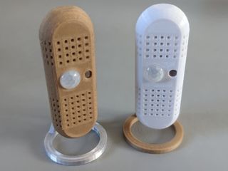
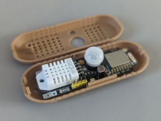
Case not supplied with development board
For customers with a 3D printer we have uploaded a custom case to Thingyverse which can be printed out on a standard 3D printer. You can find the STL files here:
https://www.thingiverse.com/thing:6027205
Downloads:
For more information including Arduino setup instructions, library, and sketches please see the product forum post here
This relay module is designed for the ESP-01s ESP8266 module. It features a 6 pin IDC socket...
The ESP8266-D1 is a wireless 802.11 (Wifi) microcontroller development board compatible with...
The ESP-01S is an updated version of the popular ESP-01 module, a compact and powerful Wi-Fi...
This amazingly priced wireless module allows any microcontroller to connect to a 802.11b/g/n...
This amazingly priced wireless module allows any microcontroller to connect to a 802.11b/g/n...
This adapter board is designed specifically for the ESP8266 ESP-07, ESP-08 and ESP-12 2.4GHz...
This amazingly priced wireless module allows any microcontroller to connect to a 802.11b/g/n...