ESP-07 ESP8266 Serial Wifi...
This amazingly priced wireless module allows any microcontroller to connect to a 802.11b/g/n...
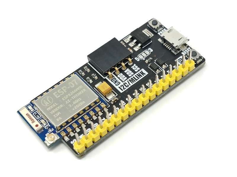


The Hobby Components ESP8266 breakout module is a general purpose development board incorporating an ESP8266 (ESP-07) wireless microcontroller. It breaks-out the ESP07’s IO pins to a convenient single in-line header making it breadboard or prototyping board friendly.
There are two versions available, HCDVBD0044 supplied with both right-angle & straight pin headers unsoldered. HCDVBD0044B comes with a straight pin header already soldered in place.
mLink compatible - The module also includes an mLink header allowing it to be easily expanded via our range of mLink modules. Connect displays, keypads, relays, and sensors all with no soldering required.
Programming - The module is compatible with the Arduino IDE via the board manager feature (see below for Arduino setup and programming). Its main includes pins for power, GND, Tx and Rx to connect a USB to serial adapter. The serial interface also includes a level shifter so both 5V and 3.3V TTL USB adapters can be safely connected.
The Hobby Components ESP8266 breakout module is a general purpose development board incorporating an ESP8266 (ESP-07) wireless microcontroller. It breaks-out the ESP07’s IO pins to a convenient single in-line header making it breadboard or prototyping board friendly.
There are two versions available, HCDVBD0044 supplied with both right-angle & straight pin headers unsoldered. HCDVBD0044B comes with a straight pin header already soldered in place.
mLink compatible - The module also includes an mLink header allowing it to be easily expanded via our range of mLink modules. Connect displays, keypads, relays, and sensors all with no soldering required.
Programming - The module is compatible with the Arduino IDE via the board manager feature (see below for Arduino setup and programming). Its main header includes pins for power, GND, Tx and Rx to connect a USB to serial adapter. The serial interface also includes a level shifter so both 5V and 3.3V TTL USB adapters can be safely connected.
On-board push buttons for reset and program mode allow the module to be switched into program mode for uploading new sketches and then switch back to normal run mode with a press of the reset button.
Power -It can be powered either via its 5V & GND header pins or, via its 5V microUSB header.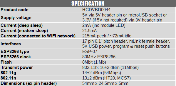
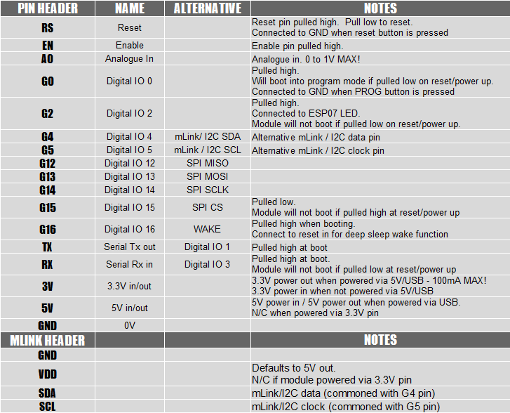
Pinout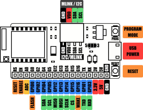
Arduino IDE setup guide:
The module is compatible with the Arduino IDE via the board manager feature. The latest version of the Arduino IDE can be downloaded from the official Arduino website here:
https://www.arduino.cc/en/software
Once installed you will need to add board support for ESP8266 devices. To do this just follow steps 1 & 2 in our blog post here:
https://blog.hobbycomponents.com/?p=937
Arduino IDE board settings:
Board: Generic ESP8266 Module
Port: The COM port of your USB interface module.
Crystal Frequency: 26MHz
Flash Frequency: 40MHz
Flash mode: DIO
Reset Method: dtr
Upload Speed: 115200
Flash Size: 1MB (FS64KB OTA:~470KB)
CPU Frequency: 80MHz
You can leave any additional settings to their defaults.
Flashing A Sketch
To interface this module to your PC you will need an additional USB to serial interface adapter. The serial interface is compatible with both 3.3V and 5V TTL adapters:
https://hobbycomponents.com/usb-interfa ... al-adaptor
https://hobbycomponents.com/usb-interfa ... rt-adapter
https://hobbycomponents.com/usb-interfa ... le-adaptor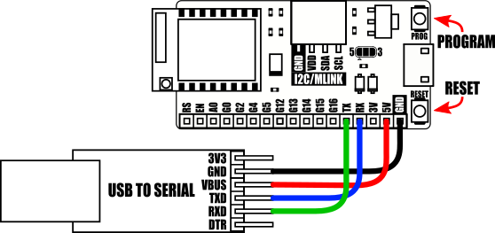
Connect the USB to serial adapter to the module's serial interface as shown above.
To put the module into programming mode, reset the module by pressing then releasing the reset button whilst holding down the program push button.
After uploading your sketch the module can be put back into run mode by pressing the reset push button.
mLink: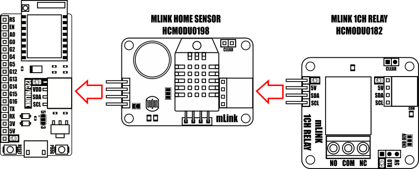
mLink example
If you wish to use this board with any of our mLink modules the mLink library can be found here:
viewtopic.php?f=58&t=3001
For more information about our mLink modules see the mLink product section of our forum here: https://hobbycomponents.com/mLink
mLink modules can be purchased from our store here: https://hobbycomponents.com/235-mlink
The mLink is also compatible with most I2C modules. Please check supply voltages and pinouts before connecting.
This amazingly priced wireless module allows any microcontroller to connect to a 802.11b/g/n...
The ESP-01S is an updated version of the popular ESP-01 module, a compact and powerful Wi-Fi...
This amazingly priced wireless module allows any microcontroller to connect to a 802.11b/g/n...
This amazingly priced wireless module allows any microcontroller to connect to a 802.11b/g/n...
This relay module is designed for the ESP-01s ESP8266 module. It features a 6 pin IDC socket...
This adapter board is designed specifically for the ESP8266 ESP-07, ESP-08 and ESP-12 2.4GHz...
The ESP8266-D1 is a wireless 802.11 (Wifi) microcontroller development board compatible with...