


ESP8266E development board
£5.99
VAT included
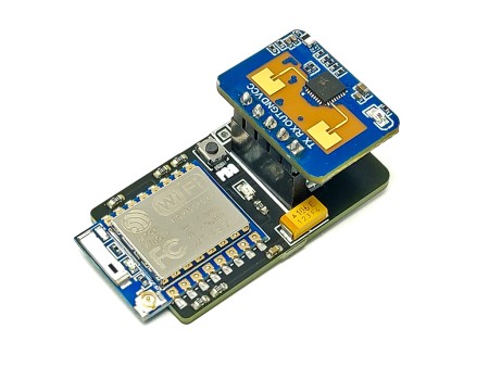
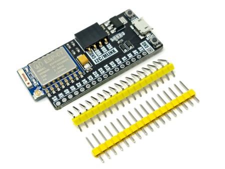
This EPS8266 development board (HCDVBD0027) is based around the very popular and low cost ESP8266 wireless (WiFi) microcontroller module. It uses the ESP-12E version of the module, which is pre-soldered to the development board. The board itself not only provides a set of standard...
This EPS8266 development board (HCDVBD0027) is based around the very popular and low cost ESP8266 wireless (WiFi) microcontroller module. It uses the ESP-12E version of the module, which is pre-soldered to the development board. The board itself not only provides a set of standard header pins, which gives access to the modules digital and analogue pins, but also includes some extra components that allow the development board to be used as a development platform for experimenting with some of the features of the ESP8266.
Additional features of this development board include:
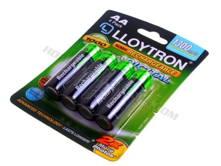
3x AA battery holder allowing the development board to be used as a portable remote sensor.
A photo-resistive sensor connected to the analogue input of the EPS8266 allowing ambient light levels to be measured.
A 3 colour RGB 5mm LED connected to digital pins 12 (green), 13 (blue), and 15 (red). When used with the PWM capability these pins allow for over a million variations.
6 surface mount LEDs which can be controlled by GPIO pins 0, 2, 4, 5, 14, and 16.
Compatible with the Arduino IDE via the board manager extension. To quickly get going we have provided an Arduino setup guide on our blog site here.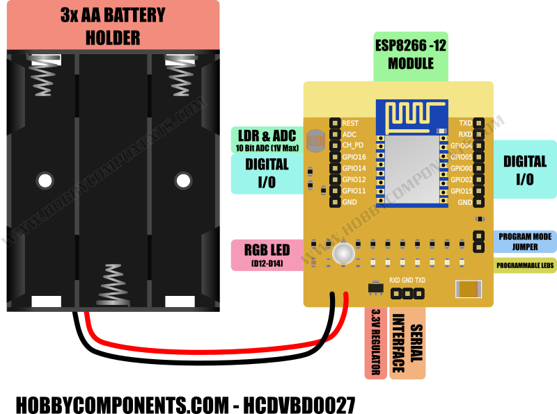
ESP8266 Module Features:
• 802.11 b/g/n
• Integrated low power 32-bit MCU
• Integrated 10-bit ADC
• Integrated TCP/IP protocol stack
• Integrated TR switch, balun, LNA, power amplifier and matching network
• Integrated PLL, regulators, and power management units
• Supports antenna diversity
• WiFi 2.4 GHz, support WPA/WPA2
• Supports STA/AP/STA+AP operation modes
• Supports Smart Link Function for both Android and iOS devices
• SDIO 2.0, (H) SPI, UART, I2C, I2S, IR Remote Control, PWM, GPIO
• STBC, 1x1 MIMO, 2x1 MIMO
• A-MPDU & A-MSDU aggregation & 0.4s guard interval
• Deep sleep power <10uA, Power down leakage current < 5uA
• Wake up and transmit packets in < 2ms
• Standby power consumption of < 1.0mW (DTIM3)
• +20 dBm output power in 802.11b mode
• Operating temperature range -40C ~ 125C
• FCC, CE, TELEC, WiFi Alliance, and SRRC certified
Notes:
To program the ESP8266 the supplied jumper should be fitted to the programming header. In normal operation this jumper must be removed.
To put the ESP8266 into programming mode cycle either the power supply or the reset pin whilst the programming jumper is inserted.
When in programming mode the RGB LED will be a blue-green colour.
When inserted, the programming jumper will connect GPIO pin 0 to ground. You should therefore avoid configuring GPIO pin 0 as an output.
GPIO maximum current = 12mA
GPIO maximum input voltage = 3.6V
The ADC is capable of measuring analogue input voltages between 0V and 1.1V
Lots of further information, including an example sketch is available on our support forum here.
HCDVBD0027
Specific References
You might also like
13 other products in the category
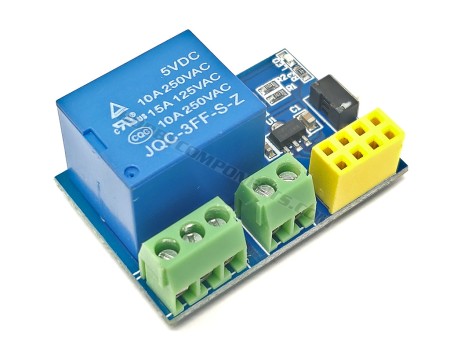
ESP-01S / ESP01S Relay...
This relay module is designed for the ESP-01s ESP8266 module. It features a 6 pin IDC socket...
£3.99
£3.79
- On sale!
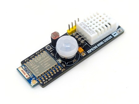
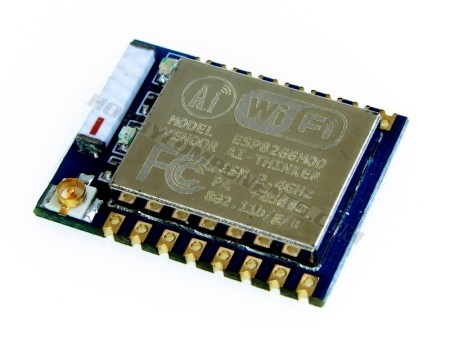
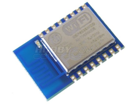
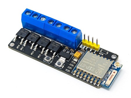
ESP-07 ESP8266 Serial Wifi...
This amazingly priced wireless module allows any microcontroller to connect to a 802.11b/g/n...
£2.99
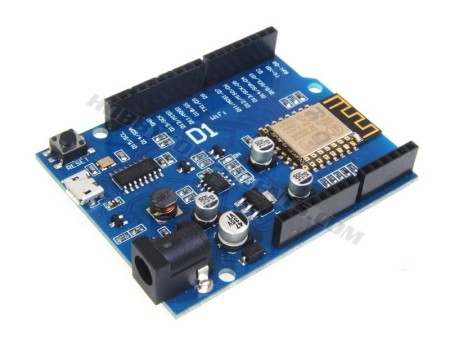
ESP8266-D1 Arduino...
The ESP8266-D1 is a wireless 802.11 (Wifi) microcontroller development board compatible with...
£4.99
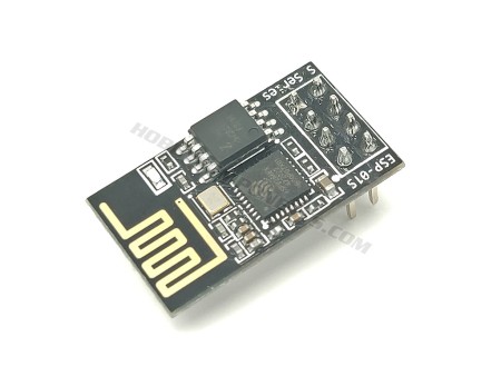
ESP-01S / ESP01S ESP8266...
The ESP-01S is an updated version of the popular ESP-01 module, a compact and powerful Wi-Fi...
£3.99
£2.79
- On sale!
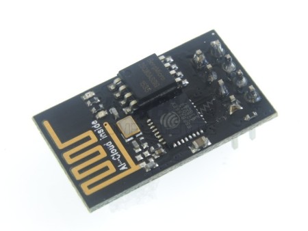
ESP-01 (ESP8266) wireless...
This amazingly priced wireless module allows any microcontroller to connect to a 802.11b/g/n...
£3.69
£3.29
- On sale!
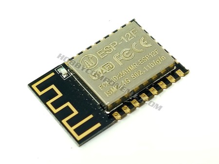
ESP-12 (ESP8266) wireless...
This amazingly priced wireless module allows any microcontroller to connect to a 802.11b/g/n...
£2.59
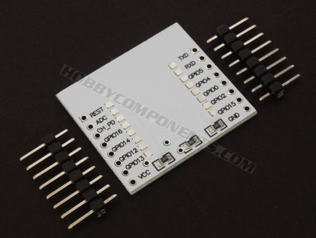
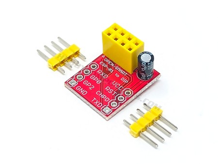
Prototyping adapter for...
This adapter board is designed specifically for the ESP8266 ESP-07, ESP-08 and ESP-12 2.4GHz...
£0.99
£0.59
- On sale!

This EPS8266 development board (HCDVBD0027) is based around the very popular and low cost ESP8266 wireless (WiFi) microcontroller module. It uses the ESP-12E version of the module, which is pre-soldered to the development board. The board itself not only provides a set of standard...