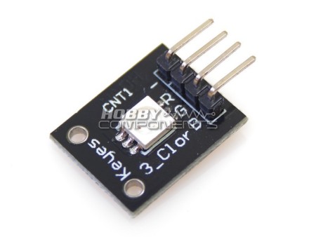
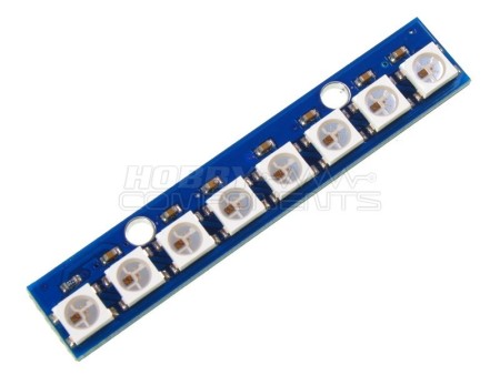
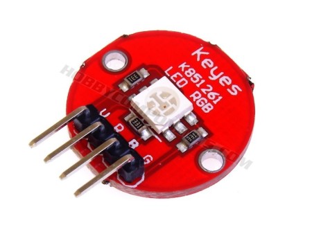
- 3-color LED Module
- With red, green and blue output
- Great for DIY project
THIS MODULE DOES NOT INCLUDE CURRENT LIMITING RESISTORS. This allows the module to be used with a range of supply voltages but you must drive the LED's via an appropriate current limiting resistor otherwise damage to the LED's will occur. We will be adding an example of how to correctly drive the LED's to this page soon.
Please note that the current version of this module has a screen print error showing wrong colour order for the pinout. Please see the table below for the correct pinout.
Red LED Vf : 2V (approx)
Green LED Vf : 3V (approx)
Blue LED Vf : 3V (approx)
Red LED Max Ifmax : 20mA
Green LED Max Ifmax : 20mA
Blue LED Max Ifmax : 20mA
| PINOUT |
|---|
| PIN |
DESCRIPTION |
| 1 |
GREEN LED |
| 2 |
RED LED |
| 3 |
BLUE LED |
| 4 |
GND |
EXAMPLE CODE
ARD_RGB_LED_MODULE_HCARDU0021_Example.pde
/* FILE:    ARD_RGB_LED_MODULE_HCARDU0021_Example.pde
   DATE:    04/07/12
   VERSION: 0.1

This is a simple example of how to use the HobbyComponents RGB LED module
(HCARDU0021). The module has 3 separate LED's (Red, Green & Blue) which
Can be individually driven by applying a voltage to the appropriate module pin.
This example uses the standard Arduino analogWrite (PWM) function to cycle
through the full range of colours this module is capable of producing.
Please be aware that this module does NOT include current limiting
resistors and therefore you should not connect this module directly to the
Arduino DIO pins.

SENSOR PINOUT:

PIN 1: GREEN LED +Ve
PIN 2: RED LED +Ve
PIN 3: BLUE LED +Ve
PIN 4: GND

You may copy, alter and reuse this code in any way you like but please leave
reference to HobbyComponents.com in your comments if you redistribute this code. */


#define BLUE_LED_DIO 11     /* Select the DIO for driving the BLUE LED */
#define RED_LED_DIO 9       /* Select the DIO for driving the RED LED */
#define GREEN_LED_DIO 10    /* Select the DIO for driving the GREEN LED */

/* Initialise serial and DIO */
void setup()
{
  /* Configure the DIO pins used by the analogWrite PWM function */
  pinMode(BLUE_LED_DIO, OUTPUT);
  pinMode(RED_LED_DIO, OUTPUT);
  pinMode(GREEN_LED_DIO, OUTPUT);
}

/* Main program loop */
void loop()
{
  int k;

  /* Slowly reduce the red LED's intensity and at the same time
     increase the green LED's intensity */
  for (k = 0; k <=255; k++)
  {
    analogWrite(RED_LED_DIO,255 - k);
    analogWrite(GREEN_LED_DIO, k);
    delay(10);
  }

  /* Slowly reduce the green LED's intensity and at the same time
     increase the blue LED's intensity */
  for (k = 0; k <=255; k++)
  {
    analogWrite(GREEN_LED_DIO,255 - k);
    analogWrite(BLUE_LED_DIO, k);
    delay(10);
  }

  /* Slowly reduce the blue LED's intensity and at the same time
     increase the red LED's intensity */
  for (k = 0; k <=255; k++)
  {
    analogWrite(BLUE_LED_DIO,255 - k);
    analogWrite(RED_LED_DIO, k);
    delay(10);
  }
}