MAX471 GY-471 3A Current...
The MAX471 module (HCSENS0041) is a complete, bidirectional, highside current-sense amplifier...
- Currently Out of Stock


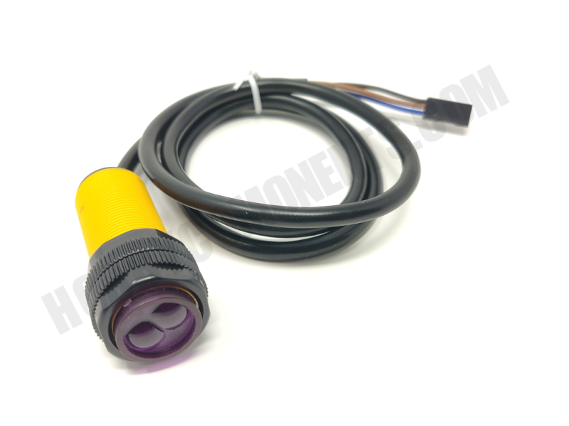
Transmitter and receiver in one photoelectric sensor. The sensor has an adjustable detection distance and visible light interference. It is easy to use and is ideal for panel mounting.
Transmitter and receiver in one photoelectric sensor. The sensor has an adjustable detection distance and visible light interference. It is easy to use and is ideal for panel mounting.
We also stock a bracket, which is perfect for easy mounting of the sensor (HCSENS0007) and also allows easy mounting to one of our robot smart cars.
Electrical Characteristics:
Supply Voltage: 5VDC
Supply Current: The 100mA
Range: 3-80CM
Size: 17mm x 45mm
Lead Length: 45cm
Wire colour codes:
BRN = 5V
BLU = GND
BLK = OUT
Output:
High = triggered
LED:
On when not triggered
Setup instructions:
With nothing obstructing the sensor adjust the multi-turn screw at rear of sensor until the LED switches from off to on. The sensor should then be calibrated for its current environment.
PLEASE NOTE: As this is an infra-red sensor it can be affected external sources of infra-red light such as sunlight.
Maximum range will be affected be environmental conditions and reflectiveness of sensed object
Example Arduino Sketch::
The MAX471 module (HCSENS0041) is a complete, bidirectional, highside current-sense amplifier...
The TSL2561 (HCARDU0102) Luminosity sensor module is a light to digital interface module. The...
The DHT21 digital temperature sensor is one of the commonest from the range of DHT temperature...
This is a very simple module that contains a magnetic reed switch which will close its...
- Photosensitive diode
- Working power: + 5V
- Working current: < 10mA
-...
This water level sensor / float switch can be used to sense when a liquid has reached a set...
This Platinum thermal resistance probe is an accurate, sensitive, and stable temperature...
This module has been designed as an alternative to the PIR motion detectors commonly used in...
Optical endstop providing a contactless and reliable alternative to the mechanical...
An excellent little module for detecting the speed of a motor. Ideal for our 2- and 4-wheeled...